OrangePi: Difference between revisions
(→Python) |
(→Python) |
||
| Line 73: | Line 73: | ||
<pre> | <pre> | ||
import OPi.GPIO as GPIO | import OPi.GPIO as GPIO | ||
import time | |||
GPIO.setmode(GPIO.BOARD) | GPIO.setmode(GPIO.BOARD) | ||
GPIO.setup(11, GPIO.OUT) | GPIO.setup(11, GPIO.OUT) | ||
# turn it off | |||
GPIO.output(11,GPIO.HIGH) | |||
# turn pin 11 on and wait 5 seconds | |||
GPIO.output(11,GPIO.LOW) | |||
time.sleep(5) | |||
#turn it back off | |||
GPIO.output(11,GPIO.HIGH) | GPIO.output(11,GPIO.HIGH) | ||
GPIO.cleanup() | GPIO.cleanup() | ||
</pre> | </pre> | ||
Latest revision as of 04:49, 13 April 2018
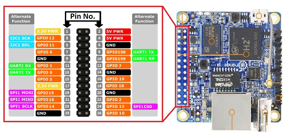
OrangePi Zero Pinout
Using GPIO w/ Orange PI
GPIO can be modified from the command line using WiringOP:
git clone https://github.com/zhaolei/WiringOP.git -b h3
cd WiringOP
chmod +x ./build
sudo ./build
Documentation can be found in the man pages or here: http://wiringpi.com/the-gpio-utility/. Test the tool using:
gpio readall
 +-----+-----+----------+------+---+-Orange Pi+---+---+------+---------+-----+--+
 | BCM | wPi |   Name   | Mode | V | Physical | V | Mode | Name     | wPi | BCM |
 +-----+-----+----------+------+---+----++----+---+------+----------+-----+-----+
 |     |     |     3.3v |      |   |  1 || 2  |   |      | 5v       |     |     |
 |  12 |   8 |    SDA.0 | ALT5 | 0 |  3 || 4  |   |      | 5V       |     |     |
 |  11 |   9 |    SCL.0 | ALT5 | 0 |  5 || 6  |   |      | 0v       |     |     |
 |   6 |   7 |   GPIO.7 | ALT3 | 0 |  7 || 8  | 0 | ALT5 | TxD3     | 15  | 13  |
 |     |     |       0v |      |   |  9 || 10 | 0 | ALT5 | RxD3     | 16  | 14  |
 |   1 |   0 |     RxD2 |  OUT | 1 | 11 || 12 | 0 | ALT3 | GPIO.1   | 1   | 110 |
 |   0 |   2 |     TxD2 | ALT5 | 0 | 13 || 14 |   |      | 0v       |     |     |
 |   3 |   3 |     CTS2 | ALT3 | 0 | 15 || 16 | 0 | ALT3 | GPIO.4   | 4   | 68  |
 |     |     |     3.3v |      |   | 17 || 18 | 0 | ALT3 | GPIO.5   | 5   | 71  |
 |  64 |  12 |     MOSI | ALT4 | 0 | 19 || 20 |   |      | 0v       |     |     |
 |  65 |  13 |     MISO | ALT4 | 1 | 21 || 22 | 0 | ALT3 | RTS2     | 6   | 2   |
 |  66 |  14 |     SCLK | ALT4 | 0 | 23 || 24 | 0 | ALT4 | CE0      | 10  | 67  |
 |     |     |       0v |      |   | 25 || 26 | 0 | ALT3 | GPIO.11  | 11  | 21  |
 |  19 |  30 |    SDA.1 | ALT4 | 0 | 27 || 28 | 0 | ALT4 | SCL.1    | 31  | 18  |
 |   7 |  21 |  GPIO.21 | ALT3 | 0 | 29 || 30 |   |      | 0v       |     |     |
 |   8 |  22 |  GPIO.22 | ALT3 | 0 | 31 || 32 | 0 | ALT3 | RTS1     | 26  | 200 |
 |   9 |  23 |  GPIO.23 | ALT3 | 0 | 33 || 34 |   |      | 0v       |     |     |
 |  10 |  24 |  GPIO.24 | ALT3 | 0 | 35 || 36 | 0 | ALT3 | CTS1     | 27  | 201 |
 |  20 |  25 |  GPIO.25 |  OUT | 1 | 37 || 38 | 0 | ALT5 | TxD1     | 28  | 198 |
 |     |     |       0v |      |   | 39 || 40 | 0 | ALT5 | RxD1     | 29  | 199 |
 +-----+-----+----------+------+---+----++----+---+------+----------+-----+-----+
 | BCM | wPi |   Name   | Mode | V | Physical | V | Mode | Name     | wPi | BCM |
 +-----+-----+----------+------+---+-Orange Pi+---+------+----------+-----+-----+
Use the table to determine the correct pin. The wPi column is the ID for the pin. For output, use the following command to change the corresponding pin's mode gpio mode <pin> in/out/pwm/clock/up/down/tri:
gpio mode 2 out
Once the mode is set correctly, use:
gpio write 0 1
To turn the flag off, and then:
gpio write 0 0
Python
Follow the instructions at https://opi-gpio.readthedocs.io/en/latest/
Install PIP
sudo apt-get install python-pip
Install the GPIO library:
sudo pip install --upgrade OPi.GPIO
A simple python script to turn the flag off or on:
import OPi.GPIO as GPIO
import time

GPIO.setmode(GPIO.BOARD)
GPIO.setup(11, GPIO.OUT)

# turn it off
GPIO.output(11,GPIO.HIGH)

# turn pin 11 on and wait 5 seconds
GPIO.output(11,GPIO.LOW)
time.sleep(5)

#turn it back off
GPIO.output(11,GPIO.HIGH)
GPIO.cleanup()
